


Assembly aid & assembly instructions
Here you will find all instructions for our products. Subject to model and technical changes and errors excepted. All contents are protected by copyright. Reprints and publications, including extracts, are only permitted with express authorisation.Instructions for individual products can be found directly on the products or here.
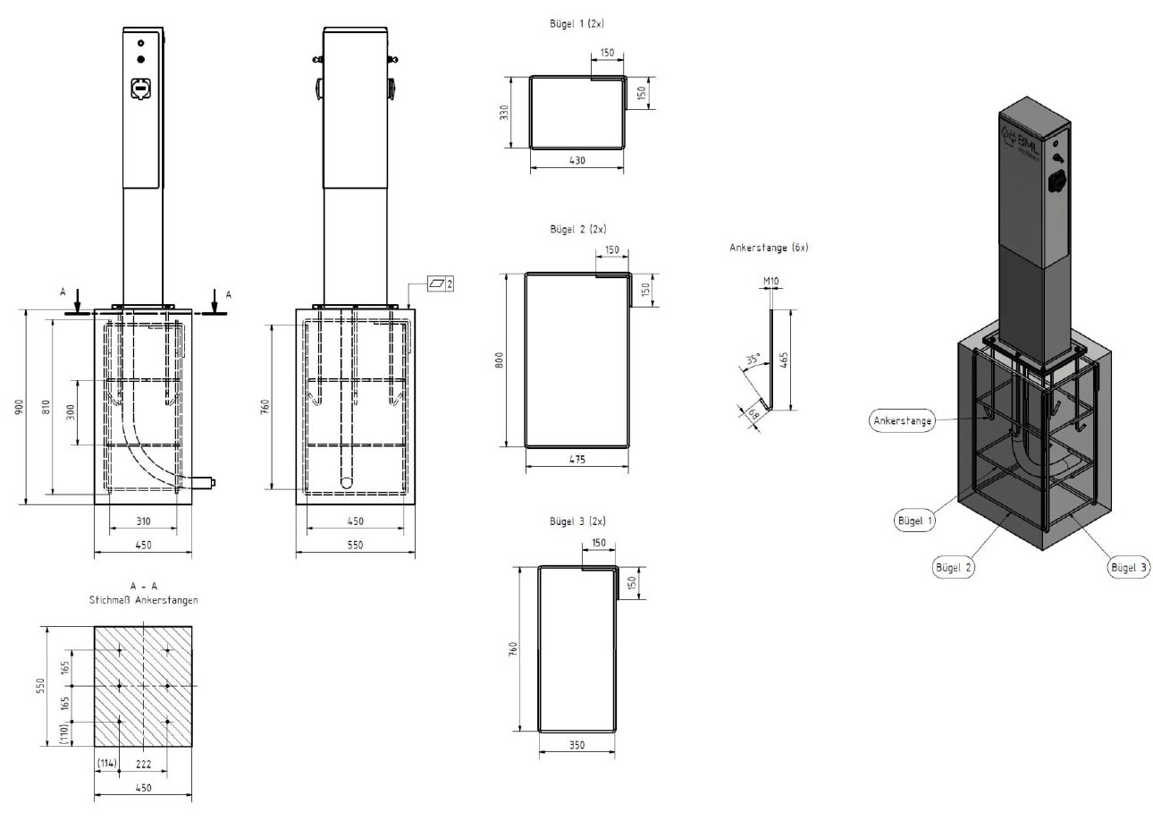
We recommend concrete foundations (B25) for free-standing systems, with the dimensions per frame side being 450 x 450 mm. For smaller systems, a continuous foundation with the following dimensions is required: system width + 450 x 450 mm. The foundation should be enlarged depending on the ground conditions. The depth of the foundation should be at least 700 mm, depending on the frost line in the soil. Before excavation, it is advisable to obtain a plan of the planned installation site from the relevant authority so that pipes, electrical cables, etc. are not damaged. Please ensure that the cables are pulled before concreting.
.jpg)
If the system is set in a concrete foundation, the depth of the embedded parts should be 350 mm - 500 mm.
If the system is screwed on to a concrete foundation, you must use bolt anchors (diameter 10 - 12 mm) or equivalent.

We recommend our cover rosettes to finish the screw connection and the transition into the ground.

Foundation requirements
The foundation must meet the following requirements:
Concrete: C25/30 XF1 XC2
Rebar: BST 500 S wire & slash; 10 mm
Foundation reinforcement plan
The reinforcement plan is shown in the following figures. In particular, ensure that the foundation is sufficiently level:
Ladesäulen Plug / Draw
Ladesäule Close

1. Check
The wall on which the letterbox system is to be mounted must be clean and even. It is important to ensure that the wall is sufficiently strong. Depending on its size, a letterbox weighs between 5 and 18 kg.
2. Measure
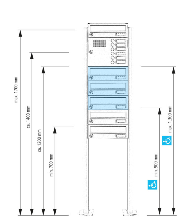
Measure the mounting holes on the back of the system. Transfer these measurements to the wall. Please note the installation height prescribed by DIN 13724. The centre line of the lowest insertion opening should not be below 700 mm. The centre line of the highest insertion opening should not be higher than 1,700 mm. Only in exceptional cases (barrier-free access) are 400 mm and 1,800 mm permissible as the lower and upper limits.
3. Drilling
Drill holes in the wall and insert wall plugs in the holes. Attention: The size of the holes and the type of wall plugs depend on the respective wall properties and must therefore be determined on site. If in doubt, please seek expert advice locally.
4. Screw
Open the doors of the boxes in which the mounting holes are located and insert the appropriate screws with the spacers into the dowels through these boxes. Screw the system together. This step is best done by three people.
Our in-wall systems are equipped with pre-cut cable inlets on all sides, which can be easily removed if necessary. We recommend having the in-wall system installed by a professional, as installing systems in house walls can create thermal bridges if the insulation layer is interrupted during installation.
1. Measure height and width
Measure the exact width and height from the back of the letterbox system. This is important because you need the dimensions without the plaster cover frame. Add a total of approx. 20 mm to these dimensions in both height and width and then draw a rectangle on the wall in which the system is to be installed using these dimensions. Please note the installation height prescribed by DIN EN 13724. The centre line of the lowest insertion opening should not be below 700 mm, and the centre line of the highest insertion opening should not be higher than 1,700 mm. Only in exceptional cases are 400 mm and 1,800 mm permissible as the lower and upper limits.
2. Measure depth
Now measure the overall depth of the letterbox system and add a further 5 to max. 10 mm.
3. Break out niche
Then break out a niche in the wall within the marked rectangle and to the depth of the system.
4. Fit the system
Then carefully fit the system into this niche and, if necessary, correct the niche size.
5. Drill
Bring the system into its final position and mark the drill holes on the wall. Remove the system from the niche and drill the corresponding holes in the back wall of the niche and insert the wall plugs into the holes. Caution: The size of the holes and the type of wall plugs depend on the respective wall properties and must therefore be determined on site. If in doubt, please seek expert advice on site. Tip: The system can also be attached via the side panels.
6. Screw
Now reintroduce the system into the niche, open the doors of the boxes containing the mounting holes and insert the appropriate screws into the dowels through these boxes. Screw the system together. Make sure that the plaster frame completely covers the niche.
To achieve optimal water protection for your post, the system/letterbox should be equipped with the above-mentioned panels or a rain canopy. If possible, the letterbox or letterbox system should be located under a canopy. The post is only protected from water when it is completely placed in the box and the flap is closed. If mail is not fully inserted, moisture and dirt can get into the letterbox. It is therefore necessary to plan sufficiently dimensioned letterboxes for the upcoming demand. We offer extra letterbox depth for increased mail volumes, and we are also happy to manufacture individual special sizes. However, water can still enter the letterbox under certain extreme weather conditions (according to DIN EN 13724 up to 1ccm). This is not a reason for complaint.
Installation direction
In a letterbox system, the post is protected from wind and weather. However, when installing a free-standing system, make sure that the insertion front is not directly facing the weather side, in line with good craftsmanship tradition.
Our complete sets are usually ready for connection! We already program the complete sets at our factory.
However, we always recommend having the electrical installation carried out by an electrician. Please always refer to the operating instructions provided by the manufacturer for wallboxes, intercoms and video systems!
Camera, intercoms or wallbox preparation
We offer preparation of cameras, intercoms and wallboxes from various manufacturers for our systems. The preparation does not include any end devices; it involves the provision of the screw fittings, drill holes and perforations. This means that you can easily mount your end device.
General warnings
Our light and bell modules, as well as our light and bell push buttons, may only be operated at a maximum of 12-24 volts! A transformer with VDE certification must be used! Higher voltages can endanger human life and will void the warranty. Only components with a 100% permissible duty cycle may be connected to the buttons and modules! Failure to observe this warning may result in: - fire hazard - personal injury - destruction of components. Electrical devices may only be installed and assembled by a qualified electrician! Please check whether the power consumption of the standard power supply unit is sufficient for your planned connection (e.g. for bell, intercom, light control as well as cable length and cross-section).
Light/bell push DESIGNER
Light/bell push as a single push-button is used to switch on the lighting in the entrance area and/or a stairwell or to operate a signal generator.
Terminal L1/L2 = LED - illuminated ring 5-24V AC/DC
Terminal C/NO = contactor
Current consumption approx. 40mA
Switching capacity max. 50mA @ 50V DC 1W
Light/bell push button BASIC
Light/bell push buttons as single push buttons are used to switch on the lighting in the entrance area and/or a stairwell or to operate a signal generator.
Terminal +/- = LED illuminated ring 3-24V AC/DC, LED illuminated ring ‘light’ 6-36V 110V/220V AC/DC
Terminal NC/NO = contactor
Current consumption approx. 20mA
Switching capacity max. 5A @ 250V AC
LED light
Please note that our LED lights, if they have not been completely pre-wired and connected by us, may only be operated at 12 volts DC. Other voltages will destroy the LED light and shorten its lifespan.
Attention: Always ensure the correct polarity
If your letterbox is in its original packaging, your keys are in the letterbox (take them out through the insertion slot) or in the enclosed bag (this also contains the assembly aid and other small parts). Every letterbox that leaves our premises is carefully checked and packed. A declaration of care is enclosed by the employee who manufactured your new product. If you still cannot find your key, please feel free to contact us.
Standards & regulations
DIN EN 13724
When planning a letterbox system, you should always observe the currently valid DIN EN 13724 (also known as the ‘letterbox standard’) so that you or your tenant do not have any problems receiving post.
DIN EN 13724 guarantees you:
• Easy mail delivery without bent letters or personal collection at a post office, e. B. for large DIN C4 envelopes
• Sufficient storage space for higher mail volumes
• No hassle with wet mail
• Best quality through specified and tested materials
• Security against rent reductions through standardised letterboxes
Our products are usually all tested according to this standard and marked accordingly. Only a few do not meet this standard. Find out more
Information about DIN formats that fit into the corresponding letterbox slot is cropping up more and more often. Here is a brief overview of the dimensions of the most common formats:
DIN A5: 148 x 210 mm
DIN A4: 210 x 297 mm
DIN A3: 297 x 420 mm
DIN B5: 176 x 250 mm
DIN B4: 250 x 353 mm
DIN B3: 353 x 500 mm
DIN C5: 162 x 229 mm
DIN C4: 229 x 324 mm
DIN C3: 324 x 458 mm
Material science
1.4301 is characterised by its good weldability with electrical processes. Even without heat treatment, the steel is corrosion resistant due to its low carbon content. The carbon content must be below a percentage of 0.08, although values below 0.05% are now common in practice. It can also be polished very well and is flexibly formable. It is approved for temperature stresses of up to 600 °C. Its high-quality appearance is particularly appreciated when polished.
X5CrNi18-10 is a relatively soft, nickel-containing, non-ferromagnetic austenitic steel. To keep the material rust-free and scale-resistant, 1.4301 contains a minimum of 13% chromium.
We now use 1.4301 stainless steel for the majority of our products. Compared to galvanised steel, this has the advantage of increased durability and sustainability. Our claim for a manufactured product is that it lasts a lifetime.
The material 1.4016 is part of the stainless steel group and is also known under the designation AISI 430 or X6Cr17.
This is referred to as ferritic steel and has a maximum chromium content of 18% (minimum 16%). Ferritic steel is highly magnetic, unlike austenitic steel grades. The special property of stainless ferritic chromium steel lies in its ferritic microstructure. This is what makes 1.4016 resistant to stress corrosion, which is usually the critical point in austenitic stainless steels. The drawback is the poor weldability of the material.
The material is characterised by its good bending, deep-drawing and polishing properties. Its insensitivity to stress corrosion cracking and its basic resistance to alkaline solutions, moisture or diluted organic acids, for example, should also be emphasised. It is not resistant to corrosion in salt water.
We now use 1.4016 stainless steel for the majority of our powder-coated products that do not require welding. Compared to galvanised steel, this has the advantage of increased durability and sustainability. Our claim for a manufactured product is that it will last a lifetime.
Powder coating is a tried and tested method of refining our surfaces. In this process, electrostatically charged powder coatings are applied to the respective workpieces using a spray gun. The parts then pass through a conveyor system to be baked in the oven. At temperatures of around 180° Celsius, the structures of the powder and the coated surface bond with each other. The heating process gives the powder a high-quality, smooth or evenly structured surface. We powder-coat metal parts such as steel, stainless steel, aluminium or other electrically conductive materials.
The advantages of powder coating include high corrosion protection and strong resilience. Coated parts are impact and scratch resistant, as well as resistant to chemicals and weathering.
Powder coating is a particularly environmentally friendly surface treatment technique, because no solvents or thinners are used in powder coatings. In addition, the powder coating process saves resources because the excess paint that is applied can be reclaimed.
We use both terms interchangeably, so the abrasive rating of our products always corresponds to 240 grit. This number indicates the roughness/grain size of the abrasive. The surface is matt.

General information about electromobility
In many federal states and municipalities there are individual funding programmes. Find out about current Förderprogramme.
All about the charging process
Charging does not depend on direct current or alternating current charging, but only on the charging power in relation to the battery capacity of the electric car. If the charging power is less than or half the battery capacity, charging is assumed to be slow. Example: Battery capacity 44kWh and charging power up to max. 22kW (physically not quite correctly expressed here).
With slow charging, the time required for a full charge from 0% to 100% SOC can be approximated with the following formula:
Battery capacity in [kWh] / (charging power in [kW] * efficiency 0.9) = charging time in [h].
For simplification, a charger efficiency of 90% (= 0.9) is assumed. Depending on the vehicle model and charging power, the efficiency can be between 80% and 95%. Translated with www.DeepL.com/Translator (free version)
General information
Templates for our name tags in PDF format. You can digitally label these, print them out yourself and use them directly. We recommend printing on thicker paper or transparent film.
Only high-quality materials are selected and processed for the Briefkasten Manufaktur, which guarantees durability and timeless elegance. Please bear in mind, however, that noble materials in particular need to be cared for. Even normal environmental influences can cause soiling and even surface changes. Particularly in industrial conurbations or at sea, deposits in the form of flash rust can occur and the material can be attacked. Here, systems should be cleaned and maintained more frequently.
Stainless steel
One of the materials we use for our products is stainless steel. This steel is characterised by its resistance to water, water vapour, humidity, food acids and weak organic and inorganic acids when used and maintained as intended. After the letterbox has been installed, it should be cleaned for the first time to remove any dirt caused by storage, transport or construction or installation work. Protective layers of paper, foil or adhesive residues must be completely removed after assembly, as they can lead to corrosion. The letterbox should then be maintained approx. every 3 - 4 weeks. We recommend our stainless steel maintenance spray. Please note: The cleaners must not contain any hydrochloric acid, chlorides or hydrocarbons. Under no circumstances should steel wool, steel brushes or similar be used for cleaning stainless steel, as such aids damage the protective surface and enable the formation of extraneous rust through abrasion. Corrosion caused by flash rust is excluded from the warranty. Stainless steel surfaces must always be cleaned in the direction of the rust.
Aluminium
Oxidising or mechanically acting cleaning agents must not be used, as they attack the anodised layer. Caution! Protect aluminium parts from cement, lime, plaster, etc.
Glass/Plexiglass
Acrylic glass (Plexiglas) must not come into contact with organic solvents such as thinners, alcohols, fuels, etc. Glass cleaners also usually contain alcohols. Glass cleaners also usually contain alcohols. For cleaning, use only clear water with a few drops of washing-up liquid and a soft sponge. Dust must never be wiped away dry.
Powder coatings
Water and small amounts of a mild cleaner can be used to clean the surface of the powder coating. If absolutely necessary, a small amount of turpentine substitute can also be used. Then rinse with water and a mild cleaner!
Painted surfaces
We recommend weekly cleaning and sealing with car wax at least four times a year for painted surfaces! For cleaning, use only clear water with a few drops of washing-up liquid and a soft sponge. Painted surfaces must also be dried and sealed with car polish. Caution: Do not use cleaning agents containing vinegar.
Lock and hinges
Please only maintain the cylinder lock with a special lock care spray. This way you can enjoy a functioning letterbox lock for a long time. It is best to clean and maintain letterbox hinges twice a year
You can find care and cleaning products in our care guide.
Please note: The cleaners must not contain salts, chlorides or hydrocarbons. Under no circumstances should steel wool, steel brushes or similar be used for cleaning stainless steel, as such aids damage the protective surface and enable the formation of extraneous rust through abrasion. Corrosion caused by rust film is excluded from the warranty.
You can find spare parts for each product directly on the product pages below the product description.
In the Spare parts shop for letterboxes from Manufaktur Lippe, you will find important spare parts for letterbox systems and letterboxes, from nameplates to letterbox locks.